PICAXE Class Project
A PICAXE 20M2 chip was used in a TIMARA Class Project. Everything was soldered onto a small circuit board. This 20-pin chip was able to accommodate all the following devices:
A serial interface for programming the chip from any computer.
A MIDI Output.
A 3 square wave Audio Output from a 3 resistor mixer.
A Cadmium Cell light controller.
A Trimmer Pot controller.
Powered by a 9-volt battery
The pdf document shows the circuit diagram and a short BASIC program that outputs both MIDI and Audio.
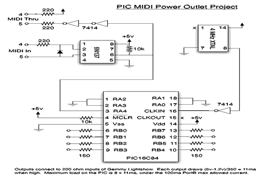
MIDI AC Controller
A Christmas LightShow controller was bought in an after season sale. This provided an already built safe enclosure for 6 AC power outlets along with opto-isolator/triac circuits for turning the AC outlets on and off from 6 simple 0 to 5 volt control signals.
The Lightshow Controller was retrofitted with a PIC16C84 microcontroller and a MIDI Input circuit. The PIC is programmed to detect MIDI Note On commands for 6 specified key numbers from the MIDI Input stream and translate those key off and key on commands to 6 control output lines.
The PIC16C84 does not have a serial port. The serial Midi Input data is gathered from a single PIC input line a bit at a time with the serial timing accomplished by carefully counting processor cycle times in the program. A MIDI parsing routine pulls from the MIDI Input stream only those KEY ON commands that we are interested in.
Alternatively, you could use an Arduino Uno board and program it with the available MIDI Library and a Midi Callback program. Use the same MIDI circuit shown below, but connect it to Digital Input Pin 0 (RX) of the Arduino Board.
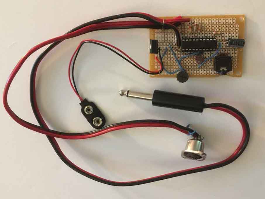
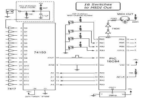
MIDI Trigger
The MIDI Trigger Box has 16 inputs for connecting to simple switch devices and one MIDI output. The inputs accept 1/4 inch phone plugs. When the plug's tip makes a connection with the sleeve, a Midi Note On is sent out on one of 16 Note values. When the connection is broken, a Midi Note Off signal is sent for that note.
A common application here at Oberlin Conservatory is a sound or video installation using foot pads as the switches. The audience members walk around the installation area causing Midi Note On and Off signals to be generated depending on where they are stepping. These Midi signals are sent to a computer running Max programming language which controls what the participants see and hear.
This circuitry employs a PIC single chip microcomputer. The software watches for changes on the 16 inputs and sends out Midi signals when it sees a change. Timing for the Midi output signal is built by carefully counting PIC instruction cycle times.
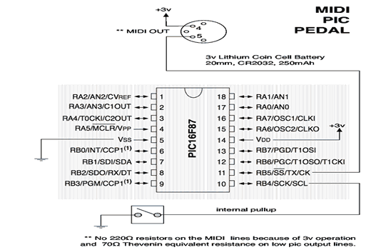
MIDI Pedal
This is a simple foot pedal switch converted to transmit MIDI Note On commands.
The pedal's 1/4" phone plug is replaced with a MIDI plug and the circuitry requires only a switch, a 3volt coin cell battery, and an 18 pin PIC16F87. No other components are necessary.
The programming makes use of the PIC16F87's internal 8MHz clock, and its internal UART serial transmitter set to the MIDI baud rate. An interrupt based program allows the processor to sleep when there is no activity so there is hardly any drain on the battery. A pdf paper below describes how interrupts work on the PIC16F87.